260°C
Electrical relative thermal index
Long-term electrical property retention for VICTREX™ 450G, tested to UL 746B. The operating temperature of a loaded part depends on its application.
Additive manufacturing for medical, aerospace, automotive and semiconductor programmes, from a single prototype to production runs.
Polyether ether ketone
Strength, thermal stability and chemical resistance in one engineering polymer. From lightweight industrial components to specialised medical grades, the material starts with the job. We print and machine it to your drawing.
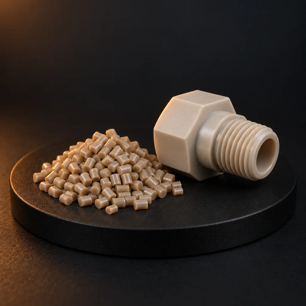
260°C
Long-term electrical property retention for VICTREX™ 450G, tested to UL 746B. The operating temperature of a loaded part depends on its application.
≈71%
1.30 g/cm³ for PEEK 450G versus 4.42 g/cm³ for Ti-6Al-4V. An equal-volume material comparison; final part weight depends on the design.
98 MPa
VICTREX™ 450G at 23 °C, tested to ISO 527-2. A precise material reference for strength-led design; printed performance also depends on build direction and processing.
Implant grade
Specialist materials such as Invibio PEEK-OPTIMA™ have biocompatibility data for implantable applications. Medical devices require the specified grade, manufacturing process and device qualification.
Material references: VICTREX 450G ↗TIMETAL 6-4 ↗Invibio PEEK-OPTIMA ↗
Compare grade data, applications and manufacturing considerations.
Polyether ether ketone
Strength, chemical resistance and electrical insulation for wear parts, fixtures and functional components.
VICTREX 450G datasheet ↗REFERENCE GRADE / VICTREX™ 450G
23 °C · ISO 527-2
23 °C · ISO 527-1
1.8 MPa · unannealed · ISO 75-2/Af
Manufacturer resin data. Heat deflection measures deformation under load; it differs from continuous service temperature.
Wear parts, fixtures, insulators and demanding functional components.
Load direction, service temperature and chemical exposure. Build orientation and finishing set the performance of the finished part.
High-temperature extrusion for complex geometry; machining for precise interfaces and stock-based parts.
Manufacturer reference grades, not a stock list. Resin and printed-coupon data use different test conditions; specify the grade and build requirements for your part.
Quote a PEEK part ↗Bring us the operating conditions.
Temperature + durationLoad + directionChemicals + exposureInspection + traceability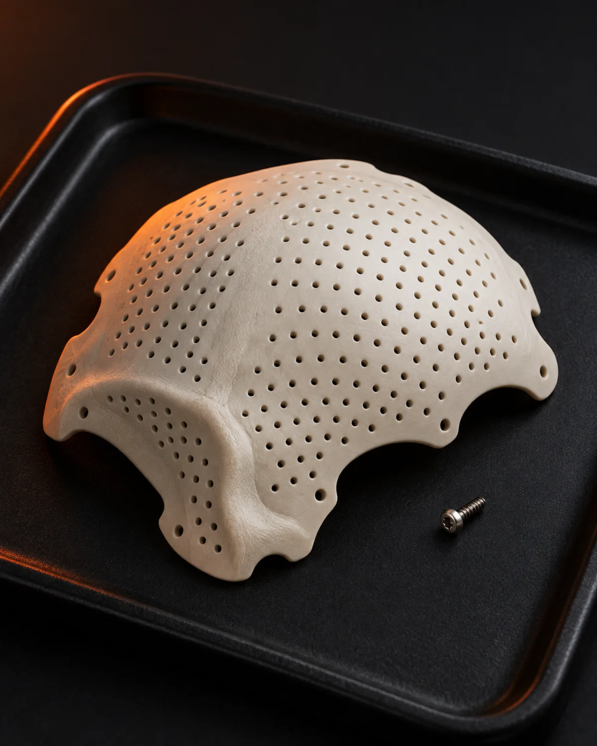
Complex anatomical geometry, surgical guides and development prototypes, built around the specified material and drawing.
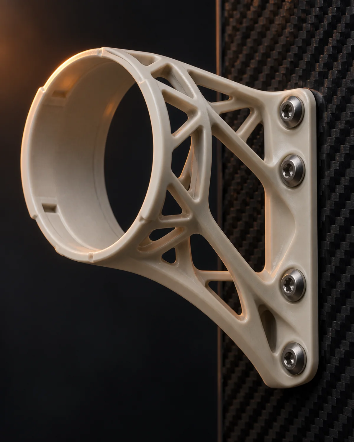
Lightweight brackets, housings and ducting, with build orientation and finishing planned around the assembly.
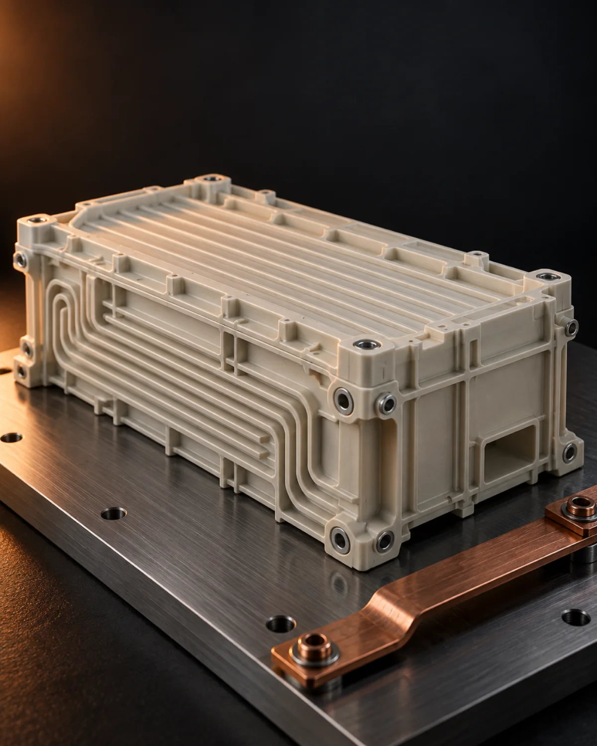
Functional prototypes, fixtures and housings for automotive development and production programmes.
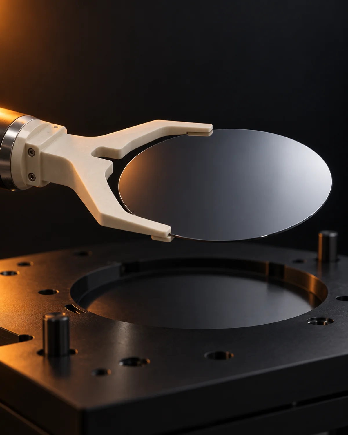
Wear-resistant jigs, fixtures and end-effectors for automation and cleanroom robotics.
Manufacturing methods

Fused deposition for robust functional prototypes and production parts in PEEK, PEKK, ULTEM and engineering polymers.
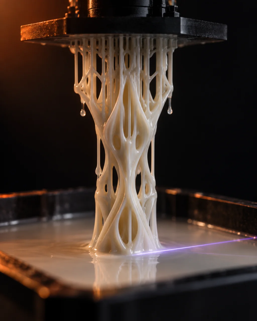
Stereolithography for ultra-fine detail and smooth surface finishes.
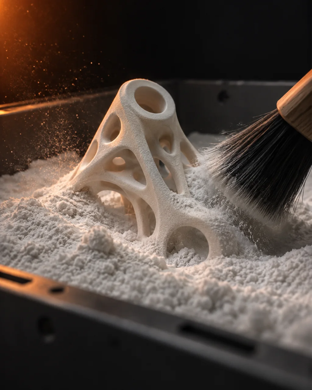
Selective laser sintering for complex geometries with no support structures.
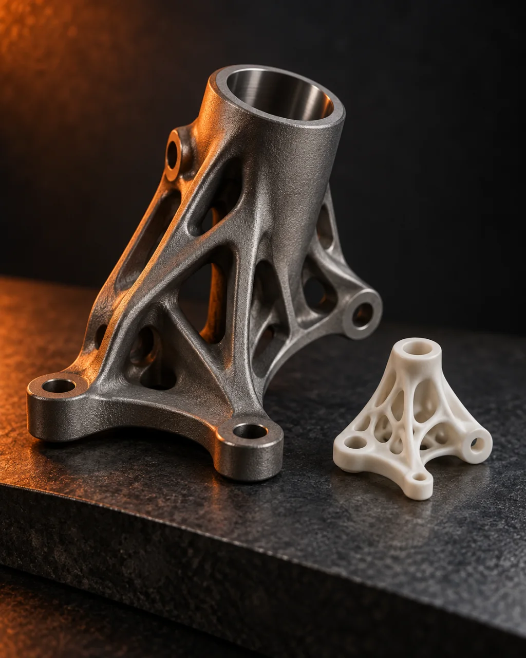
Metal, polymer and ceramic materials, including full-colour parts.
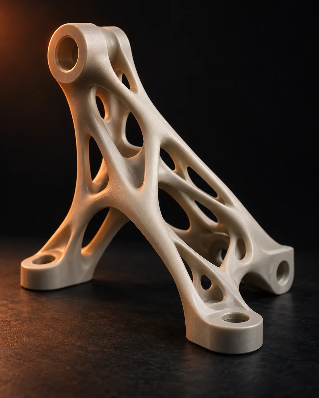
AI-driven topology optimisation for maximum performance with minimum material.
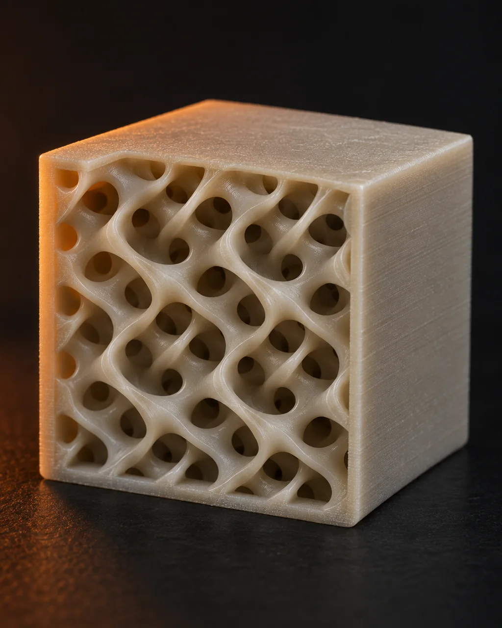
Engineered lattice and infill patterns for lightweight structural integrity.
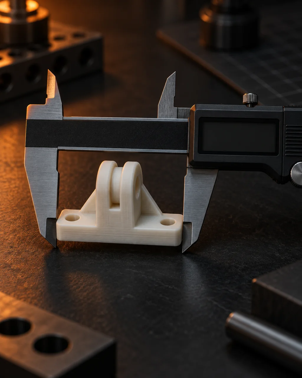
Design for additive manufacturing. We rework parts so they print right the first time.
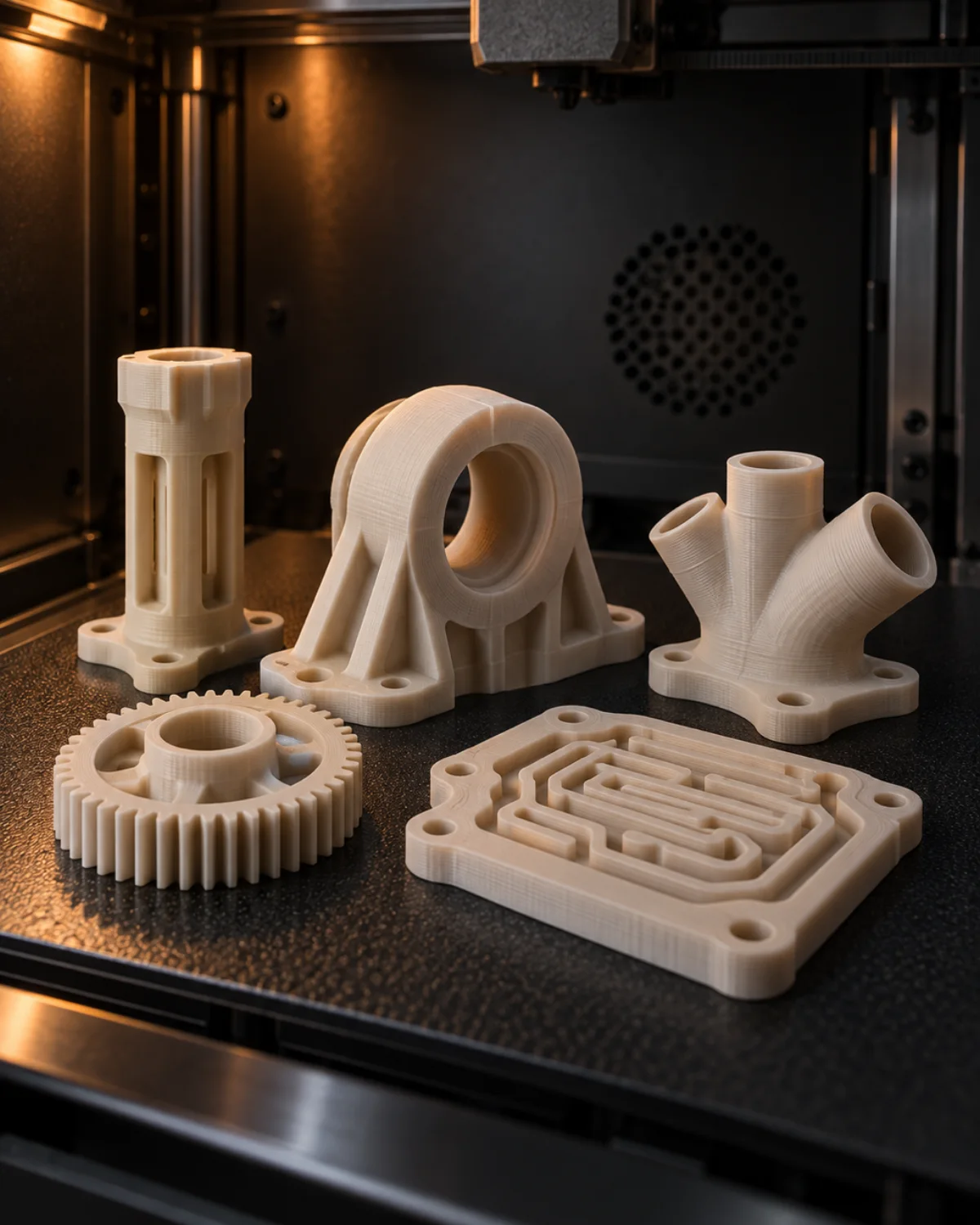
FDM, SLA, SLS, MJF
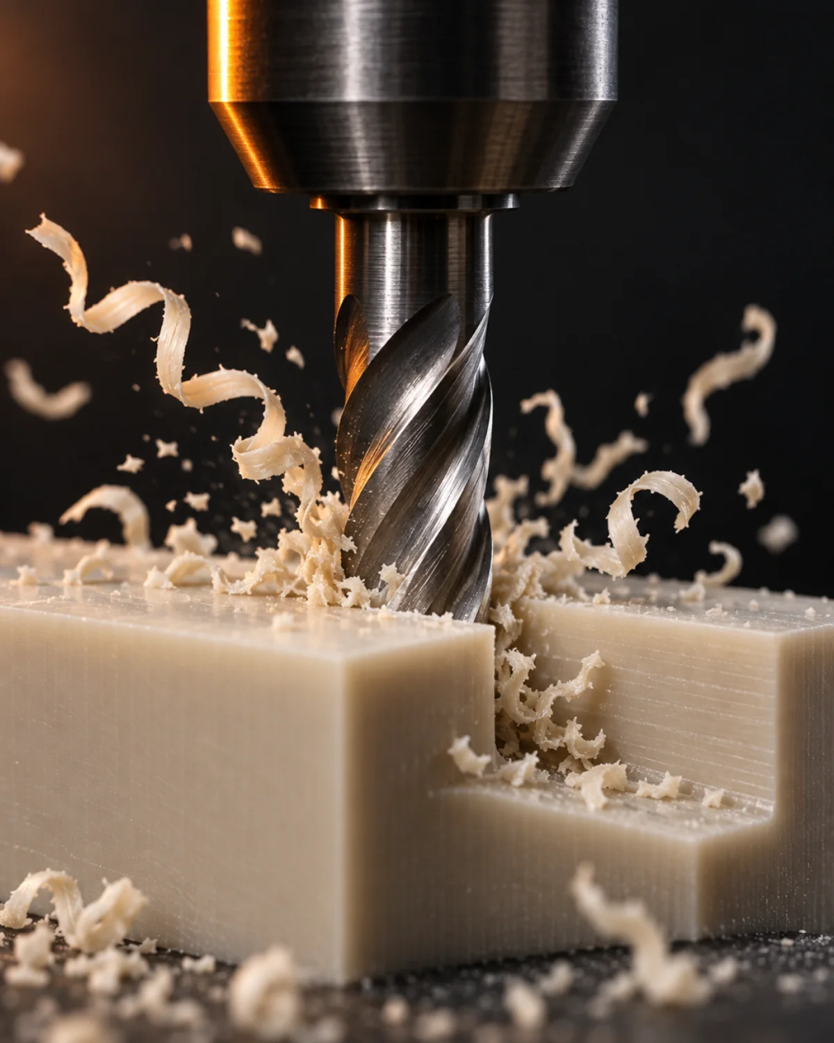
Milling, turning and post-processing
Prototype and production tooling
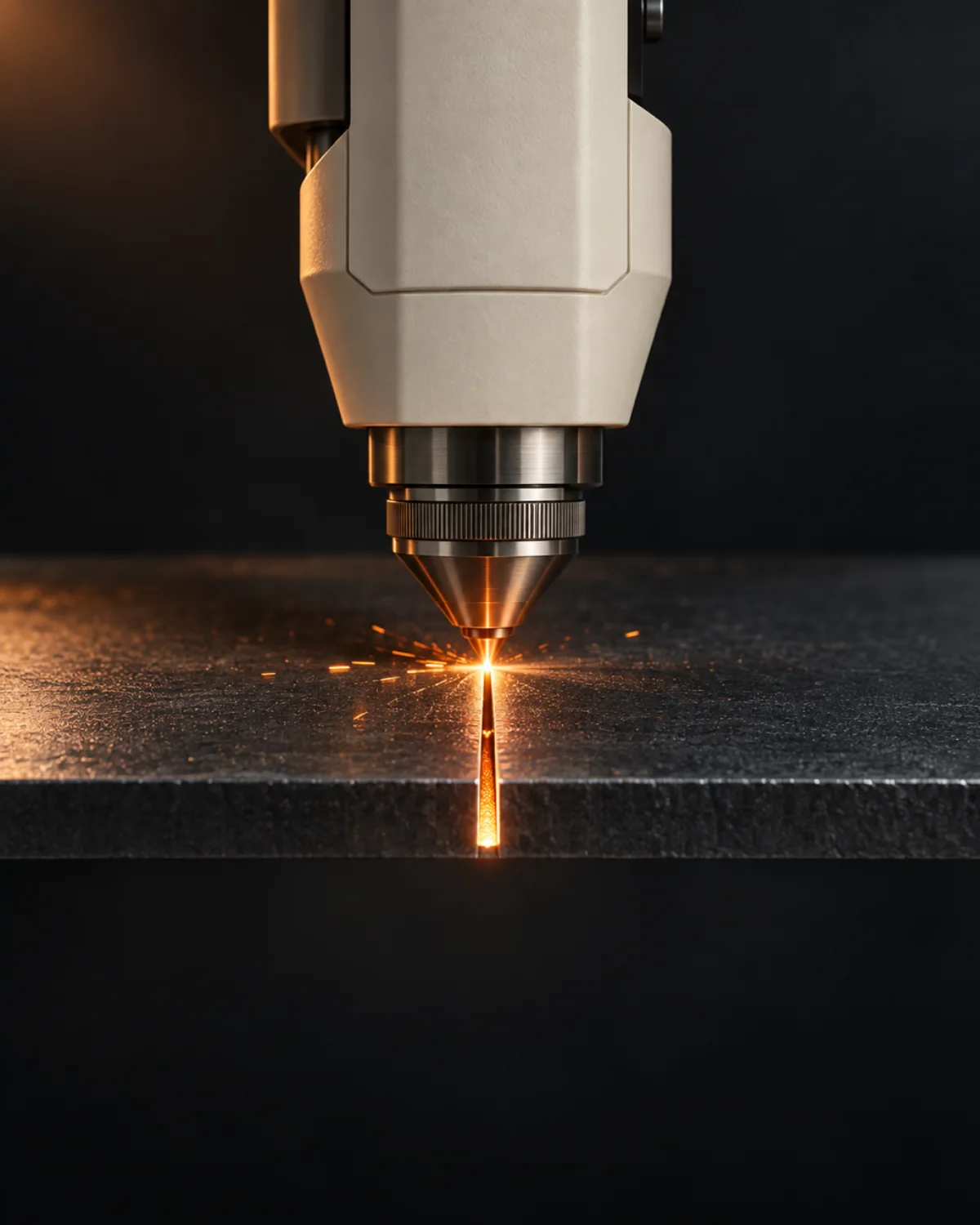
Laser cutting, bending, post-processing
From single prototypes to production runs. Figures shown are starting capabilities; geometry, material, quantity and finishing determine the final tolerances and lead time in your quotation.
The engineering, up close
Turn it. Section it. Understand it.
Explore the decisions inside five very different parts.
Concept models showing engineering features; not customer case studies.
Design study / PF.003
A simple mount makes a useful test of the questions that matter: where the load goes, how the tool reaches it, and what needs checking.
Quality / from drawing to delivery
Drawing revision, datums, fits and material grade establish the build requirements. We review the dimensions that matter to the assembly before manufacture.
Printing, CNC finishing and post-processing work together. Mating faces, holes and threads receive the finishing specified on your drawing.
Dimensional inspection checks the specified features against their acceptance limits. Include a measurement report in your brief when you need a record of the results.
Revision control, inspection scope and sampling requirements give repeat orders a defined baseline. Specify batch traceability and supporting documents with the order.
Need NDT, SPC or certification documents? Include the required method or standard in your brief. Your quotation sets out the inspection scope, scope of supply and documentation.
Inside an inspection report
Select a feature to follow its drawing dimension, measured value and acceptance result.
The reading falls within 59.90–60.10 mm. The drawing defines the allowed range and measurement method.
Mark the critical dimensions and specify the report, sampling and traceability you need. We include the agreed inspection scope in your quotation.
Add inspection requirements ↗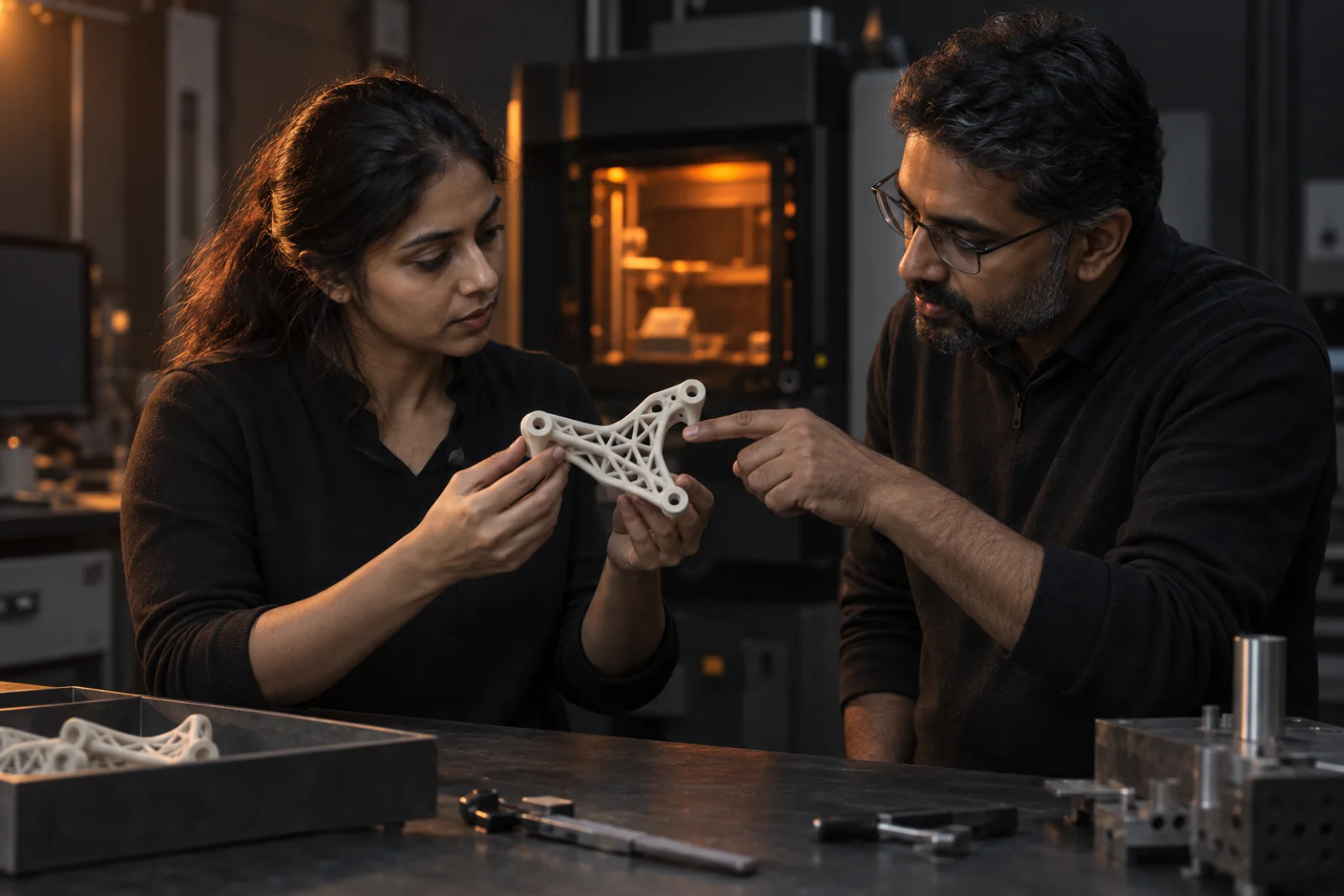
Turn a difficult geometry into a part you can test. We combine design for additive manufacturing, material selection and prototype builds to refine fit, function and manufacturability before production.

Co-Founder and Director
Thirty-seven years across HVAC, building management systems, electronics manufacturing services and additive manufacturing. Leads strategic alliances and business development, and has built companies from the ground up to high-volume production.
Founder
Three decades in regional rural banking, retiring in 2024 as Assistant General Manager at Karnataka Grameena Bank with operations across ten districts. Advises on governance, compliance and organisational development. Active with the Rotary Club of Hunsur and the Inner Wheel Club of Mysore Gold.

Choose PEEK when low weight, chemical resistance, wear or electrical insulation drive the design. VICTREX 450G has a crystalline density of 1.30 g/cm³ and a tensile yield stress of 98 MPa at 23 °C. These are manufacturer resin values; the grade, load case and manufacturing route determine finished-part performance. See the material guide for test conditions and sources.
Send STEP or IGES for quoting and design-for-additive review. STL or 3MF are suitable for print-ready geometry. Include a drawing with critical dimensions, tolerances and finishing requirements.
No. We print single prototypes and support low-volume production. Injection moulding covers 1 to 1,000,000 parts once volumes justify tooling.
Printed parts start from 1 business day; CNC machining and sheet metal from 5 business days. Quotes are returned within 24 hours of receiving a complete brief. Material, geometry, quantity and finishing determine the delivery date in your quotation.
Our starting capabilities are ±0.3% with a ±0.3 mm minimum for 3D printing, to ±0.020 mm for CNC machining, and to ±0.1 mm for sheet metal. Geometry, material and finishing determine the final tolerances in your quotation. Printed parts can be post-machined for tighter interfaces.
We manufacture development prototypes and components for medical and aerospace applications. Send the drawing, material grade and required inspection records with your brief. For regulated applications, the quotation states the applicable qualification, certification scope and release requirements.
Start a project
A drawing, an idea, or a component that needs to do more. Send your brief for a manufacturing route, price and lead time.
info@printforge.co.in +91 98441 14767 #101/102, Ananda Kuteera, Insight Academy Rd